| Home Sitemap All Articles Glossary |
Flow
Networks Case Study:
Fluid Network Design, Integration, and Tuning
by JM Tarpoff, PE, President,
J Tarpoff Corp, 513-932-9777 jtarpoff@tarpoff.com
Abstract
This case study shows the importance of checking fluid network designs before
the components are purchased and installed. The study also shows how to tune
a network as well as how to design a new fluid network from a blank sheet.
Background
An outside engineering firm had designed a water based cooling system for cooling
electrical equipment and large rotating MG sets located within an electrical
testing laboratory. The system consisted of a network of PVC pipe hung from
the laboratory roofing trusses and powered by one single stage centrifugal pump.
A plate and frame heat exchanger removed heat from the system through an interface
with the larger site-wide cooling system which used cooling towers to remove
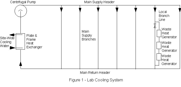
its heat. The laboratory network consisted of a main supply header and a main
return header with many branches in parallel all having the same flow area but
differing lengths and pipe components. See Figure 1.
The plan was to design, on an as needed basis, simple cooling network branches for each heat load (electrical equipment), regardless of where it may be located within the lab. The local branches would then connect to the main supply branches. Some of the local branches had multiple heat loads resulting in a series of loads within a single main supply branch.
As a new local branch was added (or subtracted), the network system resistance characteristics changed affecting flow rates within the other main supply branches as well as the pump discharge flow. The design engineer from the outside engineering firm had not considered the requirement to balance flow and had not designed throttle valves and flow meters into each of the main supply branches as a means to balance the flow.
My job centered on designing the first of several new local branches. During the layout process of the new sub-network, it became obvious that the line resistance was higher than the other main supply branches and would lead to inadequate flow within this branch.
Solution Steps
As a first step, a mechanical engineering review of the vendor's network design
had to be conducted to find any other discrepancies. Areas of keen interest
were: checking the estimates for the expected heat loads and matching this to
the designed flow rate, verifying the heat transfer capacity of the chosen heat
exchanger, verifying that the system could be drained and flushed, estimating
the expected resistances in each of the main supply branches after local branches
were added, and determining the system characteristics for verification of the
chosen pumping capacity. Other concerns were checked such as piping corrosion
resistance, pipe and hangar structural adequacy, operating temperature limitations
for all components including the PVC pipe, and type and placement of temperature
monitoring and alarms.
Each piece of electrical equipment is assigned a power loss value that can be translated into BTUs. The total estimated BTUs of waste heat was accurately specified by the electrical engineers owning the equipment to be tested. In addition, an estimate for proposed future expansion of the laboratory had been made and was added to the total estimate for waste heat. This laboratory "growth" factor was 50% and was thought to be reasonable and practical.
Next, the amount of water needed to remove the waste heat was calculated. This value will vary according to the temperature differential between the cooling water and the hot surface of the exchanger within the electrical equipment. Also, during summer, the cooling water temperature of the cooling system will be higher because the site-wide cooling water will not be able to drive the water temperature below ambient due to the use of an outdoor cooling tower. Therefore, the maximum expected differential temperature between the inlet and exit of the electrical equipment will be no higher than 10F° when all the equipment is running and the outdoor ambient temperature is 90°F. Using these values and the specific heat of water, a mass flow rate is established for the lab cooling system and a preliminary pump size is chosen. Ideally, a comfortable operating temperature differential would be 4F°. The maximum water temperature was, therefore, set to be 100°F which compared favorably to the thermal limits specified for all piping components plus a safety factor.
Pumps are specified from the manufacturers with discharge and suction pipe sizes. It is, therefore, important to determine the preliminary pump size in order to have the pipe size at the discharge and suction available for use during layout of the system piping network
The local branches designed to connect to the main supply branches had the smallest cross sectional areas because they required a smaller flow rate. An estimate of the worst case main supply branch line resistance was made from these branches. Because multiple electrical cabinets would reside in series within a branch, a worst case branch line resistance was made and assumed for each of the main supply branches. This branch line resistance was calculated from the accumulated K factors of each and every valve, elbow, straight pipe, reducer, diffuser, tee and obstruction to flow resulting from temperature probes and flow meters. The value was then assigned to each main branch supply line and combined in parallel to get an equivalent resistance value representing all the waste heat generators. K factors can be determined from Crane's Technical Paper No. 410, "Flow or Fluids", or other references. The resistance values for the remainder of the network can now be calculated from the elbows, straight pipe lengths and other associated piping components and combined in series to reach an equivalent network resistance. A total system pressure drop can be calculated from the equivalent network resistance and the required flow rate to determine a single point on the system characteristic curve of Head Loss v. Flow Rate. The entire curve can be developed by varying the flow rate and recalculating Keq, as needed, and the associated head loss. The pump can now be chosen by matching the system characteristic and the pump characteristic Head-Flow curves.
Now that we know how to perform a network design analysis, we know that throttle valves and flow meters need to be placed in each of the main supply branches in order to raise the resistance in unused supply lines. This allows flow to be furnished to the branches as required to remove the waste heat and maintain the targeted ΔT across the cooled equipment.
Results
The design review verified that the flow system designed by the outside engineering
firm met the specifications for waste heat removal except for the placement
of throttle valves and flow meters in the main supply branch lines.
In order to bring the fluid system into compliance with good network design, a butterfly valve was added to each of the main supply branches. Flow rates were determined during flow balancing using ultrasonic flow meters. The ultrasonic flow meters were chosen in an effort to reduce the cost of adding electronic flow meters directly into each branch line. Ultrasonic flow meters work well with PVC pipe and can be moved from branch to branch. In comparison with conventionally installed flow meters, more effort is required during the flow tuning process since the ultrasonic flow meters must be set up each time they are moved to a branch. However, the cost savings in equipment justifies the effort. Any valve can be used to control or throttle flow, however, butterfly valves have a wider range than most other valves, except true throttle valves, for throttling flow.
Lessons Learned
Design reviews should be conducted regardless of who performs the original design.
Even if a design is provided by an outside engineering firm or any other group
of experts with or without professional engineer licenses, it should be check
by others during a design review
All branch lines need throttle
values and some means of reading flow rates in systems requiring changes to
flow rates in network branches. Only when network flow rates and the demand
for flow are not expected to change, can branches be designed for fixed flow
and have no means of flow adjustment.
About the author:
JM Tarpoff, PE launched J Tarpoff Corp after a successful ten years in mechanical engineering design and analysis career with Bechtel Bettis (formerly Westinghouse Electric) in Pittsburgh, 3.5 years at GE Aviation / Aircraft Engines and two years in manufacturing / mechanical engineering at P&G in Cincinnati gaining nearly $2 million in savings from process improvements. The author has been an adjunct instructor of mechanical design courses through the University of Cincinnati's Applied Science College as well as having won numerous patent disclosure and design awards.